


Quick Contact
Contact Person:
Surinder Singh
Mobile:+91-9811053684
Mobile :(+91)-9810842832
Call Us : +91-129-4024461
Link Drive Motion Press
|
|

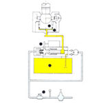
SARB Link Motion Presses:
Sarb offers a mechanical press in the form of Link Motion
Presses, comprising a variable drive arrangement. The press
boasts of a main gear which drives a crankshaft.
The press is obtainable to first shift the slide toward the
work piece at high speed, and subsequently get the work done
at low speed before quickly retrieving the slide. As soon as
the slide slows down upon moving to the working zone for the
period of the stroke, there are much less vibration, noise,
and heat from the friction between the compared with those
crank presses.
Standard Accessories Supplied With Presses
- Hydraulic overload protection
- High Torque Slide Height Adjustment Motor
- Die height Indicator
- Crank position indicator
| Model - SARB-LM | 25 | 32 | 40 | 63 | 100 | 160 | 200 | 250 | 315 | 400 | |||||||
| A | B | A | B | A | B | A | B | A | B | A | A | A | A | A | |||
| Force |
KN | 250 | 320 | 400 | 630 | 1000 | 1600 | 2000 | 2500 | 3150 | 4000 | ||||||
| Rated distance before B.D.C. |
MM | 3.5 | 2.2 | 3.5 2.2 | 4 2.2 | 5 2.5 | 5 2.5 | 6.3 | 6.3 | 6.3 | 8 | 12 | |||||
| Number of slide strokes |
SPM | 70 | 140 | 70 140 | 65 130 | 60 120 | 45 100 | 40 | 40 | 35 | 35 | ||||||
| Fly
Wheel energy |
KJ | 4.4 | 3.0 | 4.4 3.0 | 8.0 4.6 | 16.75 7.8 | 25.0 12.5 | 55.0 | 70.0 | 80.0 | 120.0 | 240.0 | |||||
| Stroke fxed |
MM | 80 | 80 | 88 | 100 | 125 | 160 | 200 | 200 | 200 | 250 | ||||||
| Variable stroke (Optional) |
MM | 8 -80 | 8-80 | 8-88 | 8-100 | 8-125 | 8-160 | 20-160 | 20-160 | 20-160 | - | ||||||
| Shut height (Stroke down , Adj. up) |
MM | 300 | 300 | 315 | 350 | 450 | 500 | 560 | 560 | 630 | 700 | ||||||
| Slide adjustment |
MM | 63 | 63 | 70 | 70 | 80 | 125 | 125 | 125 | 125 | 125 | ||||||
| Bolster area (L-RxF-B) |
MM | 630 X400 | 630 X 400 | 800 X 450 | 900 x 550 | 1000x630 | 1120x750 | 1250x800 | 1250x800 | 1450x900 | 1450x900 | ||||||
| Clear distance between uprights |
MM | 420 | 420 | 500 | 590 | 670 | 775 | 900 | ... | ||||||||
| Main motor |
KW x RPM | 2.2x1500 2.2x1000 | 2.2x1500 2.2x1000 | 3.7x1500 3.7x1000 | 5.5x1500 5.5x1000 | 7.5x1500 7.5x1000 | 15x1500 | 15x1500 | 18.5x1500 | 22x1500 | 30x1500 | ||||||
| Slide adjustment motor |
KW x RPM | 1.1x1500 | 1.1x1500 | 1.5x1000 | 1.5x1000 | 2.2x1000 | |||||||||||
| Height from floor to Top of bolster |
MM | 800 | 800 | 900 | 900 | 900 | 900 | 900 | 900 | 900 | 900 | ||||||
| Required air pressure ATM |
5.5 | 5.5 | 5.5 | 5.5 | 5.5 | 5.5 | 5.5 | 5.5 | 5.5 | 5.5 | |||||||
| Die
cushion model |
DC -72 | DC -72 | DDC - 82 | DDC -102 | DDC - 123 | 3DC - 144 | 3DC-144 | 3DC-164 | DC - 002 - | 30-125 | |||||||
| DIE CUSHION | force | KN | 17 | 17 | 44 | 70 | 100 | 200 | 200 | 270 | 300 | ||||||
| stroke length | MM | 50 | 50 | 50 | 50 | 50 | .75 | 100 | 100 | 100 | |||||||
| pressure pad area | MM | 290 x 200 | 290 x 200 | 335 X 230 | 380 x 260 | 475 X 330 | 535x425 | 600x425 | 600x475 | 850 x 520 | |||||||
| required air pressure | ATM | 7 | 7 | 7 | 7 | 7 | 7 | 7 | 7 | 5 | |||||||